Crack Growth in Polymers
Stress Concentration and
Stress Intensity Factors
The fracture strength of structural materials is often described with the Griffith model.1 This model is in excellent agreement with the observed fracture strength of brittle materials like glass and ceramics. However, for polymers and metals that undergo extensive plastic deformation it gives unrealistically low fracture energies, or in other words, the observed fracture energy is several orders of magnitude greater than the fracture surface energy of brittle materials.
In ductile or not ideal elastic materials a plastic zone develops at the tip of the crack. This plastic zone increases in size until the stress behind the tip of the crack unloads. The plastic deformation behind the crack tip results in dissipation of energy as heat. This energy has to be added to the (elastic) fracture surface energy as has been proposed by Orowan and Irwin independently (1948):
G = 2 (Γe + Γp)
where G represents the total strain energy, and Γe and Γp are the elastic and nonelastic contributions to the fracture surface energy, respectively. Assuming Griffith's energy criterion is still valid, the critical stress for crack propagation can be written as
σcr2 = G E / (π a)
where 2a is the length of the crack
and E is the Youngs or tensile modulus.
Another approach is the analysis of stress distribution around
areas of constrain such as
notches, holes, and circumferential grooves.
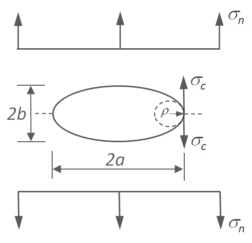
For example, for an elliptical hole in an infinitely wide plate subjected to a
normal stress, σn, the stress at the tip of the
hole, σt,
is given by
σt = σn (1 + 2 a / b)
or
σt = σn [1 + 2 (a / ρ)1/2]
where 2a and 2b are the ellipse diameter in a direction perpendicular and parallel to the external load and ρ = b2/a is the radius of curvature of the tip of the hole. For the special case of a spherical hole, the maximum stress at the hole is three time the normal stress, σt = 3 σn. Thus, a geometric discontinuity causes localized stress that is well above the average or far-field stress of the part.
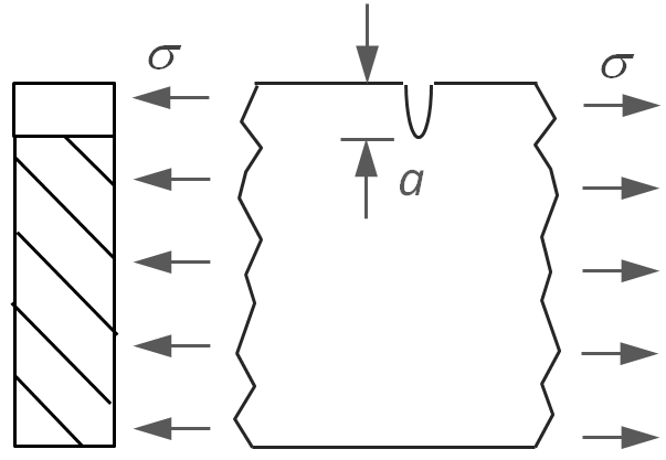
Elliptical Notch in a Plate
The ratio of the maximum stress around a geometric constraint and the nominal stress is called the stress concentration factor:
Kt = σmax / σ for normal stress (tension)
Kts = τmax / τ for shear stress (torsion)
In these equations, σmax, τmax represent the maximum stress at the edge of the defect and σ, τ are the applied farfield or nominal tensile and shear stress. In the case of an elliptical hole or elliptical grove, the stress concentration factor is simply 1 + 2 (a / ρ)1/2. In general, stress concentration factors are either obtained analytically from the elasticity theory or finite element method, or experimentally using strain gages and other devices. They can be found in many handbooks for the most common geometries.
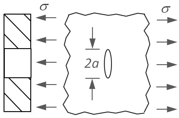
The stress concentration factor describes only local stress around macroscopic "defects" and changes in cross section (notches). The sharper the radius at the cross section change, the higher the stress concentration. Typically, these factors range from one to three. For microscopic defects, i.e. cracks and flaws, the radius of curvature can be extremely small and approaches zero for very sharp corners. Thus, the stress concentration factor becomes very large and strong plastic deformation around the crack tip can be expected. In this case, the allowable stress has to be calculated with the so called stress intensity factor. This factor is often used for fatigue calculations. It is an inherent property of the material and has to be determined experimentally for each part geometry and load condition. For a sharp crack in an infinitely wide and elastic plate the stress intensity factor is given by
KI = σ (π a)1/2
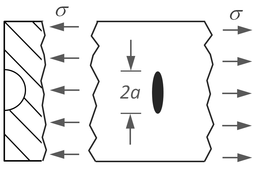
and for the criitcal stress that causes crack propagation (fracture) the condition reads
KIc = σc (π a)1/2
where KIc is the critical stress intensity factor which is a measure for the materials resistance to fracture. This parameter is also known as the fracture toughness of the material.
By comparing the equation of stress intensity with Orowan's modification of the Griffith equation we find
KI = (G E)1/2 for plane stress
KI = [G E / (1 - ν2)1/2] for plane strain
In general, stress intensity factors depend on the crack and sample geometry, and may be written in the form
KI = β σ (π a)1/2
where β is the geometry correction factor which is a function of extrinsic factors such as sample width, crack size, and load.
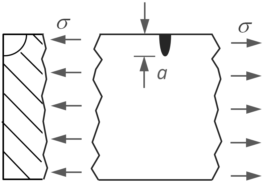
| Crack Type | Stress Intensity Factor | |
|
Elliptical Through Crack |
 |
KI = σ (π a)1/2 |
|
Semi-Circular Crack |
 |
KI = 1.12 (2σ / π) (π a)1/2 |
Semi-Circular Corner |
 |
KI = 1.122 (2σ / π) (π a)1/2 |
Edge
Through Crack |
 |
KI = 1.12 σ (π a)1/2 |
References and Notes
- A.A. Griffith, Philos. Trans. Roy. Soc. A, Vol. 221, Issue 582, p. 163 (1921)
- G.R. Irwin in Handbuch der Physik, Band VI, Elastizitaet und Plastizitaet, 1958
- M.D Lechner, K. Gehrke, E.H. Nordmeier, Makromolekulare Chemie, 1993